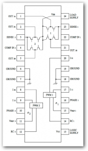
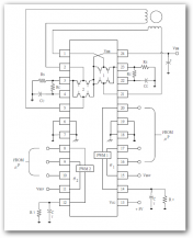
pin assignment
AMM56219 AMM56219
Features
1) Interchangeable with SGS L6219DS
2) 750mA continuous output current
3) 45V output sustaining voltage
4) Internal clamp diodes
5) Internal PWM current control
6) Low output saturation voltage
7) Internal thermal shutdown circuitry
2) 750mA continuous output current
3) 45V output sustaining voltage
4) Internal clamp diodes
5) Internal PWM current control
6) Low output saturation voltage
7) Internal thermal shutdown circuitry
Description
The AMM56219 motor driver is designed to drive both windings of a bipolar stepper motor or to control
bidirectionally two DC motors. Both bridges are capable of sustaining 45V and include internal pulse-width
modulation (PWM) control of the output current to 750mA. The outputs have been optimized for a low output
saturation voltage drop (less than 1.8V total source plus sink at 500mA).
For PWM current control, the maximum output current is determined by the user’s selection of a reference voltage
and sensing resistor. Two logic-level inputs select output current limits of 0, 33%, 67%, or 100% of the maximum
level. A PHASE input to each bridge determines load current direction.
The bridges include both ground clamp and fly-back diodes for protection against inductive transients. Internally
generated delays prevent cross-over currents when switching current direction. Special power-up sequencing is not
required. A thermal protection circuitry disables the outputs if the chip temperature exceeds safe operating limits.
The IC is supplied in either SOP24 (AMM56219) or DIP24 (AMM56219A) . Its batwing construction provides for
maximum package power dissipation in the smallest possible construction. Also, Pb free product is available
( Please refer to Marking Identification ).
Applications
Scanner, Printer


